Your Step-by-Step Guide
What Does this Guide Cover?
Understanding how a rainwater harvesting system works is essential when planning, designing or specifying a system.
In this guide, we explain the full process, including:
- Why is rainwater harvesting important
- System diagram
- Collection
- Pre-Filtration
- Storage
- Break tank
- Distribution
The following sections take you step by step through the process of delivering a reliable non-potable water supply using harvested rainwater.

Why is Rainwater Harvesting Important?
Across the UK, interest in commercial rainwater harvesting is increasing as policymakers, developers, engineers and businesses respond to two growing pressures. The first being constrained infrastructure capacity and the second being climate change. As the built environment continues to expand, reducing potable water demand and limiting the volume of stormwater entering ageing drainage networks has become increasingly important.
Rainwater harvesting addresses both challenges. In commercial and public buildings, systems can reduce mains water consumption by up to 75%. In domestic properties, savings of up to 50% are achievable. Beyond water conservation, rainwater systems help to:
-
Reduce pressure on local drainage networks
-
Lower the risk of surface water flooding
-
Cut operational water costs
-
Deliver savings without requiring behavioural change from occupants
How Does Rainwater Harvesting Work - System Diagram
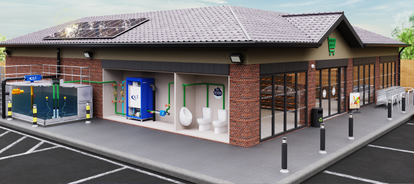
Here is a diagram showing an example of a rainwater harvesting system in a commercial building.
Collection
Step 1: Rainwater Is Collected from the Roof
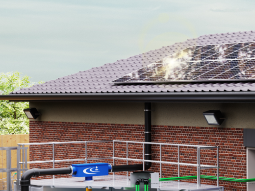
Rainwater harvesting begins at roof level. The roof surface acts as the primary collection area, capturing rainfall before it enters the drainage system.
In most buildings, the roof is the cleanest catchment surface available. As an elevated, non-traffic area, it provides the best opportunity to collect relatively uncontaminated rainwater before it reaches ground level. The quality of water collected at this stage directly influences downstream water quality and system performance.
Collection Potential and Runoff Rates
The volume of rainwater that can be collected, known as the collection potential, depends on several factors, including:
-
Roof material
-
Roof pitch
-
Presence of vegetation for green roofs
Different roof types produce different runoff coefficients:
-
Typical commercial flat roof: 80% collection potential (around 20% lost)
-
Pitched domestic roof: 90% collection potential
-
Green roof: 50% collection potential due to water absorption by vegetation
These runoff values are critical when calculating system yield and sizing the main storage tank. Considering the true collection potential in the sizing process can support long-term, reliable water savings.
Once collected, rainwater is transported via standard guttering and downpipes to the filtration stage before entering the storage tank.
Pre-Filtration
Step 2: It Passes Through Pre-Filtration
Before entering the main storage tank, rainwater is channelled through a pre-tank filter. This filter is designed to prevent leaves and larger debris from entering the tank and compromising water quality.
The pre-tank filter works by passing rainwater across a mesh screen. The screen contains small holes that prevent particles larger than 1mm from entering the tank. A 1mm (1,000 micron) mesh size is specified under BS 16941-1:2024, the British Standard for rainwater harvesting systems. This hole size is considered optimal, as it prevents most contaminants from entering the tank while maintaining a reasonable maintenance period.
The filter is typically designed to operate at approximately 90% hydraulic efficiency. This means that around 90% of the incoming rainwater passes through the filter and into the storage tank, while the remaining 10% carrying separated debris is diverted to drain.
During system installation, careful consideration should be given to filter accessibility. Pre-tank filters require periodic manual inspection and cleaning, so locating them at ground level within easily accessible chambers is essential for safe and effective maintenance.
Storage
Step 3: Rainwater Is Stored in a Tank
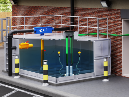
Collected rainwater is stored in a dedicated rainwater harvesting storage tank, which may be located either above ground or below ground depending on available space, site constraints and project requirements.
Tanks are typically sized to store approximately 18 days’ worth of harvested rainwater. This design approach helps ensure sufficient supply to meet the building’s non-potable water demand during periods of low rainfall, while also balancing cost, footprint and yield efficiency.
Rainwater enters the tank via a calmed inlet. This component is designed to reduce turbulence as water enters the tank, preventing disturbance of any fine sediment that settles at the base. By minimising agitation, the calmed inlet helps maintain water clarity and overall system performance. It also supports gentle circulation within the tank, helping to maintain oxygen levels and reduce the risk of stagnation.
Inside the storage tank, submersible pumps are installed to transfer rainwater into the building. These pumps draw water through a floating suction filter, which is positioned just below the water surface. This ensures that water is abstracted from the cleanest zone within the tank, above settled sediment and below any surface debris.
Break Tank
Step 4: Pumps Transfer Rainwater to a Break Tank
In many commercial and public building systems, harvested rainwater is not supplied directly from the main storage tank to points of use. Instead, it is first transferred to a smaller internal tank known as a break tank.
Submersible pumps located within the main rainwater harvesting storage tank boost rainwater into this break tank, which is typically installed inside the building for accessibility and protection.
The Role of the Break Tank
The break tank serves two primary functions: water quality protection and system reliability.
Backflow Protection and Mains Water Top-Up
The break tank provides a controlled location for mains water top-up when harvested rainwater levels are low.
Crucially, the mains water inlet is separated from the harvested rainwater by a compliant air gap. This physical separation prevents any possibility of cross-contamination. Under UK water regulations, rainwater is classified as Category 5 fluid, meaning it represents a serious health risk if backflow were to occur.
Because of this classification, harvested rainwater must never come into direct contact with the public mains supply. The air gap within the break tank ensures full compliance with water supply (water fittings) regulations and protects the integrity of the potable network.
Continuity of Supply
The second function of the break tank is to provide operational reliability.
If a component within the main storage system, such as a submersible pump or pre-tank filter, fails, the break tank can still supply water to booster pumps. In the event that harvested rainwater is unavailable, the system can automatically switch to mains top-up within the break tank, ensuring uninterrupted supply to toilets, irrigation systems or other non-potable outlets.
In systems without a dedicated break tank, a failure in the submersible pumps can prevent both rainwater and mains water from reaching points of use. For larger buildings, this presents an unacceptable operational risk.
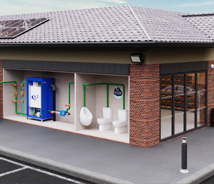
Pumps
Step 5: Rainwater Is Distributed to Toilets and Irrigation
Once transferred from the break tank, rainwater is supplied to toilets, irrigation systems and vehicle washing plants via an energy-efficient variable speed booster set. The booster set pressurises the system and distributes rainwater to the required points of use.
The booster set is sized specifically to meet the building’s demand requirements. This includes calculating the peak flow rate required to ensure all non-potable outlets can be supplied with adequate pressure and volume. Correct sizing is essential to maintain system performance and energy efficiency.
Rainwater harvesting systems can be used for a wide range of non-potable applications. Essentially, this is where the water is not intended for drinking, food preparation or personal hygiene.
For a more detailed overview of suitable applications and associated design considerations, refer to our rainwater harvesting applications guide, which outlines the technical requirements for different non-potable uses within a building.
Next Steps
How Does Rainwater Harvesting Work in Your Building? – Next Steps
We hope this guide has helped you understand more about how rainwater harvesting works. Of course, each system’s size, characteristics, and features depend on the bespoke requirements of the building. That is why we always recommend getting in touch with our experts to discuss how a system could work for your building.